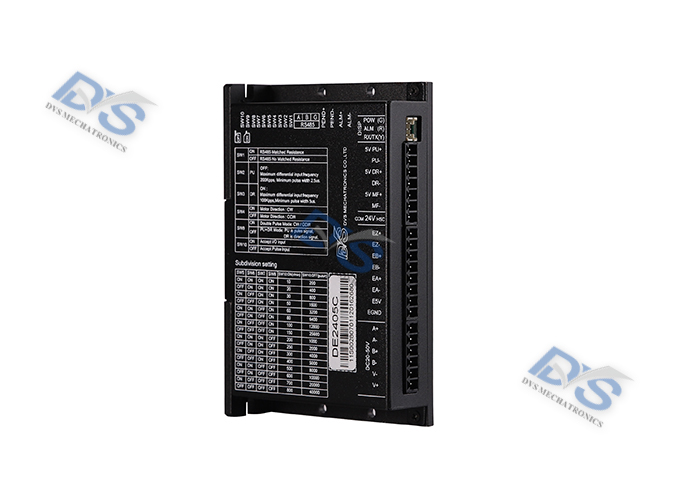
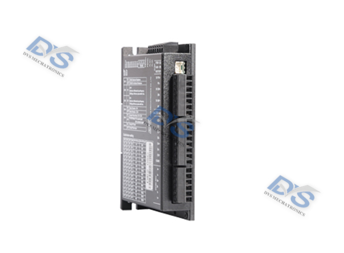
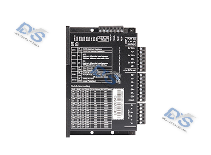
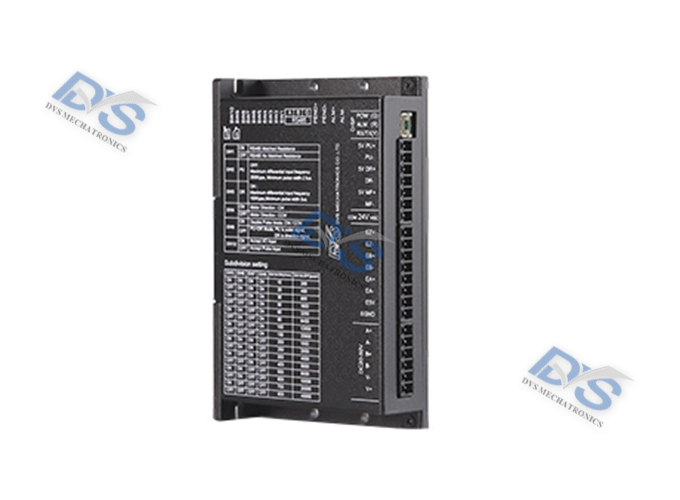
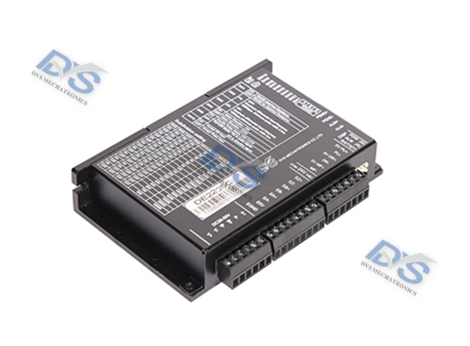
DE2205C Closed loop stepper driver
DE series pulse stepper closed-loop driver
Product Introduction
DE2205C is a new type of stepper closed-loop driver successfully developed according to market demand and development trends. It adopts a new 32-bit motor control dedicated DSP chip and pure servo principle control technology, making the motor run more smoothly and less prone to losing steps. By outputting signals and alarm signals to the outside, the controller can monitor the real-time operation status of the motor, significantly improving the high-speed performance of the motor, and successfully minimizing the heating degree and vibration amplitude of the motor, thereby better improving the machining speed and accuracy of mechanical operation. The working voltage of the driver is DC20-50V, suitable for various models of two-phase stepper motors with a current below 2.0A and an outer diameter of 42mm and below.
Technical data
Features:
1. Adopting servo principle for full closed-loop control technology and a brand new 32-bit motor control dedicated DSP chip
2. Real time control of current output based on load operation to minimize motor heat generation
3. It can drive hybrid servo motors of 42 series and below
4. Compared to open-loop stepper motors, it runs smoothly, has low vibration, and low noise
5. The maximum response frequency of the pulse can reach 200Kpps
6. Optoelectronic isolation signal input/output
7. High speed, high torque, high energy efficiency
8. The drive has an accurate operating position memory function, which does not require adjustment when stopped
9. It has protection against overcurrent, overvoltage, and tracking error exceeding tolerance
10. An external 4-digit digital display tube can be used to adjust parameters, electronic gear ratio, instruction filtering, and other parameters through the display panel
Application field:
This driver is a low-cost, high-performance servo system suitable for various large equipment and instruments. It performs better in equipment with low cost, low vibration, low noise, high precision, and high speed that users expect, such as engraving machines, wire stripping machines, marking machines, cutting machines, laser typesetting, plotters, CNC machine tools, automatic assembly equipment, etc.
Electrical parameters:
| Parameter | Minimum value | Typical value | Peak value | Unit |
| Continuous output current | 0 | 1.8 | 2.5 | A |
| Input power voltage | +20v | -- | 50v | Vdc |
| Pulse frequency | 0 | -- | 200 | KHZ |
| Input signal current | 7 | 10 | 20 | MA |
| Insulation resistance | 500 | -- | -- | MΩ |
Usage environment and parameters:
| Cooling method | Applicable environment | Storage temperature | Weight | External dimensions | |||
| Medium environment | Temperature | Humidity | Vibration | ||||
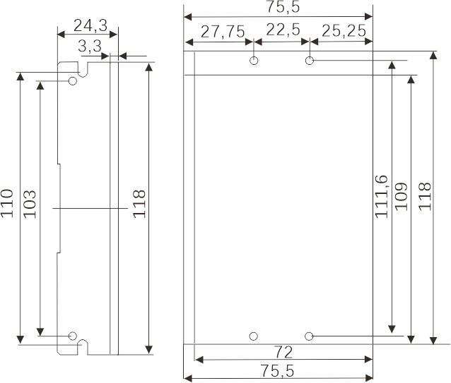
| Natural wind cooling or forced cooling | No corrosive gases or dust, and cannot be used in special environments such as magnetic fields, vacuum, etc. that contain radioactive substances | 0~ 50°C | Below 85% (without condensation) | 5.9m/s2MAX | -20°C ~ 80°C | Approximately 480 grams | 118x75.5x24.3mm³ |
External dimensions
Wiring method
Application wiring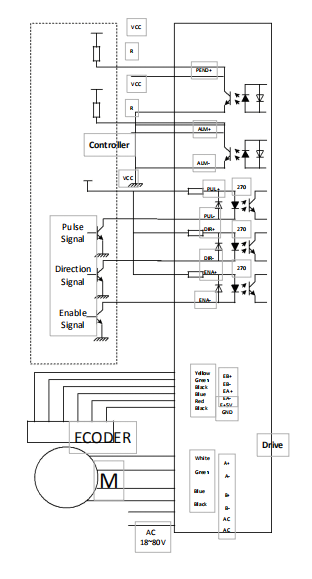
Driver interface and wiring instructions:
CN1 control signal input port
| Port | Symbol | Name | Remarks |
| 1 | 5PUL+ | Pulse signal+ | Connect to the positive end of the signal power supply, with an amplitude range of+5V. |
| 2 | 5PUL- | Pulse signal- | The falling edge is effective. Whenever the pulse changes from high to low, the motor takes one step and the input resistance is 220Ω. The requirements are: low level 0-0.5V, high level greater than 4V, and pulse width>2.5 μ S. |
| 3 | 5DIR+ | Directional signal+ | Connect to the positive end of the signal power supply, with an amplitude range of+5V. |
| 4 | 5DIR- | Directional signal- | Used to change the direction of the motor. Input resistor 220Ω, requirement: low-level 0-0.5V, high-level greater than 4V, pulse width>2.5 μ S. |
| 5 | 5ENA+ | Enabling signal+ | Connect to the positive end of the signal power supply, with an amplitude range of+5V. |
| 6 | 5ENA- | Enabling signal- | When effective (low level), turn off the motor wiring current, the driver stops working, and the motor is in a free state. |
| 7 | COM24VHSC | 24V common terminal | COM24V is a 24V common cathode and common anode input terminal. If using the common positive connection method to input a 24V pulse signal, only 24V+needs to be connected to COM24V, and 24V - needs to be connected to PU -. The common negative connection method is 24V+connected to PU+, 24V - connected to COM24V. |
CN2 signal port
| Port | Symbol | Name | Remarks |
| 1 | PEND+ | In place signal output+ | The signal output is isolated through optocouplers, with a maximum withstand voltage of 30V and a maximum conducting current of 500mA. |
| 2 | PEND- | In place signal output- | |
| 3 | ALM+ | Alarm signal output+ | The alarm signal output is isolated through an optocoupler, with a maximum withstand voltage of 30V and a maximum conducting current of 500mA. |
| 4 | ALM- | Alarm signal output- |
CN3 encoder feedback signal input port
| Port | Name | Remarks |
| 1、EZ+(Absolute value encoder+) | Encoder Z signal positive input (hardware and software changes required for absolute value encoder interface, please contact the manufacturer) | |
| 2、EZ-(Absolute value encoder-) | Encoder Z signal negative input (hardware and software changes required for absolute value encoder interface, please contact the manufacturer) | |
| 3、EB+ | Encoder B-phase positive input | yellow |
| 4、EB- | Encoder B phase negative input | green |
| 5、EA+ | Encoder A-phase positive input | black |
| 6、EA- | Encoder A-phase negative input | blue |
| 7、E5V | Encoder 5V power supply positive terminal | red |
| 8、EGND | Encoder 5V power supply negative terminal | white |
CN4 interface power supply and motor line end
| Port | Illustrate | Motor wire color | Remarks |
| A+ | Stepper closed-loop motor terminal (color must match) | Black/White | 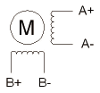 |
| A- | Red/Green | ||
| B+ | Yellow/Blue | ||
| B- | Blue/Black | ||
| DC- | black | Power supply: DC24V -50V | |
| DC+ | red | ||
CN5 RS485 Terminal Definition
| Terminal number | Symbol | Name |
| 1 | RSA | 485 communication A-phase signal |
| 2 | RSB | 485 communication B-phase signal |
| 3 | GND | Power supply ground |
Accessory products
| Electrical machinery | Drive | |||
| Machine base | Standard type | Band brake type | Torque (N.m) | Bus type |
| 42mm | DE42HB47-1000-01 | DE42HB47-1000-B-01 | 0.48 | DE2205C |
| DE42HB60-1000-01 | DE42HB60-1000-B-01 | 0.72 | ||


