

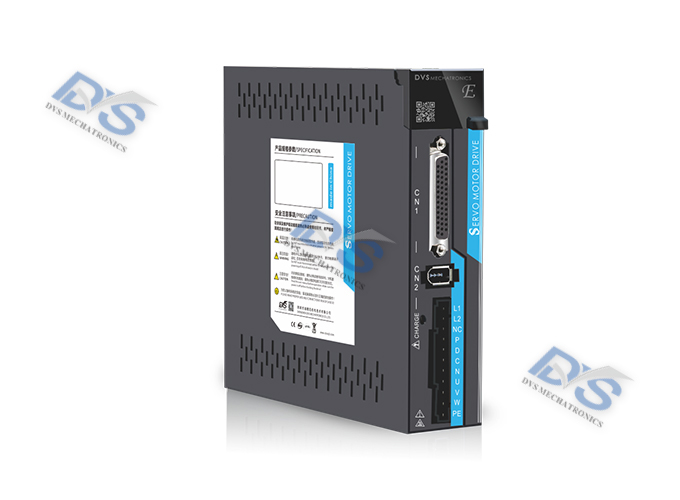
P100E-75 AC servo driver
P-series bus servo driver
Product Introduction
The P100E-75 AC servo driver is a bus type servo driver that adds bus communication function on the basis of the P series high-performance AC servo driver. Using the EtherCAT bus communication interface and based on EtherCAT slave technology, the servo system achieves real-time control and data transmission at a transmission rate of 100Mb/s. This driver has rich input and output interfaces and supports CSP, CSV, CST, PP, PV, PT, and HM operating modes. Compared with traditional pulse servo drives, this drive is particularly suitable for applications in long-distance, multi axis linkage situations, which can greatly reduce wiring and enhance the reliability of the drive operation.
Technical data
Features:
1. The working voltage is AC input voltage of AC220V ± 10%, single-phase/three-phase, 50/60Hz
2. Supports EtherCAT communication protocol, with addresses automatically allocated through the main station
3.8 single ended common positive isolation input function, with a maximum input frequency of 10KHz and an input voltage of 24V
4.6 optocoupler isolated output, with a maximum output capacity of 50mA and a maximum withstand voltage of 30Vdc.
| Model | P100E-75 | ||
| Output power | 0.75KW~1KW | ||
| Main circuit input power supply | Single phase AC220V-15%~+10% 50/60Hz | ||
| Monitoring function | Speed/current position/command pulse accumulation/position deviation/motor torque/motor current/operating status, etc | ||
| Control mode | Position control mode/speed control mode/trial operation control mode/JOG control mode/torque control mode | ||
| Protection function | Overspeed/main power supply overvoltage/undervoltage/overcurrent/overload/encoder abnormality/control power supply abnormality/position deviation, etc | ||
| Control input | 1: Negative limit 2: Positive limit 3: Origin signal 4: CCW drive inhibit 5: CW drive inhibit 6: Deviation counter reset 7: Command pulse inhibit 8: CCW torque limit 9: CW torque limit | ||
| Energy consumption braking | Internal/External | ||
| Applicable load | Less than 3 times the motor inertia | ||
| Display Operation | 5-digit LED digital display with 4 operation buttons | ||
| Input and output signals | Digital input signal | 8 DI signals can be used for signal allocation changes: servo enable, alarm clear, forward and reverse drive inhibit, zero speed box position, zero command, command reverse, speed selection, torque selection, pulse input inhibit, zero return signal, probe, forward limit, negative limit, etc | |
| Digital output signal | Six DO signals can be used for signal allocation changes: servo ready, alarm zero speed, positioning completed, and speed reached. Torque reached. Electromagnetic brake, servo operation in progress, positioning approach, torque limitation in progress, speed limitation in progress | ||
| Position control | Input method | Bus based communication | |
| Input electronic gear ratio | Gear ratio shaft accuracy: 1-131072 | ||
| Gear ratio motor accuracy: absolute values of 17 and 23 bits | |||
External dimensions

Wiring method
The following wiring diagram takes the P100E series driver as an example:

Data download
CONTACT
ADD 1: 555, 5th Floor, Liangji Building, East Ring Road, Fukang Community, Longhua Street, Longhua District, Shenzhen, China
ADD 2: 11th Floor, Building S7, Yantian Tian'an Digital City, Fenggang Town, Dongguan City, China
Tel : +86-755-26998910
E-mail : market-sales@dvsjd.com


Shenzhen Diweixun Electromechanical Technology Co., Ltd
Miss Zhang 13612901214
Phone: 0755-2699891
Email: market-sales@dvsjd.com
Address: 555, 5th Floor, Liangji Building, East Ring Road, Fukang Community, Longhua Street, Longhua District, Shenzhen, CHINA
11th Floor, Building S7, Yantian Tian'an Digital City, Fenggang Town, Dongguan City, CHINA
Copyright @ 2023 Shenzhen Diweixun Electromechanical Technology Co., Ltd. All Rights Reserve 粤ICP备2023019575号


