

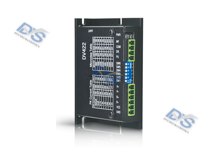
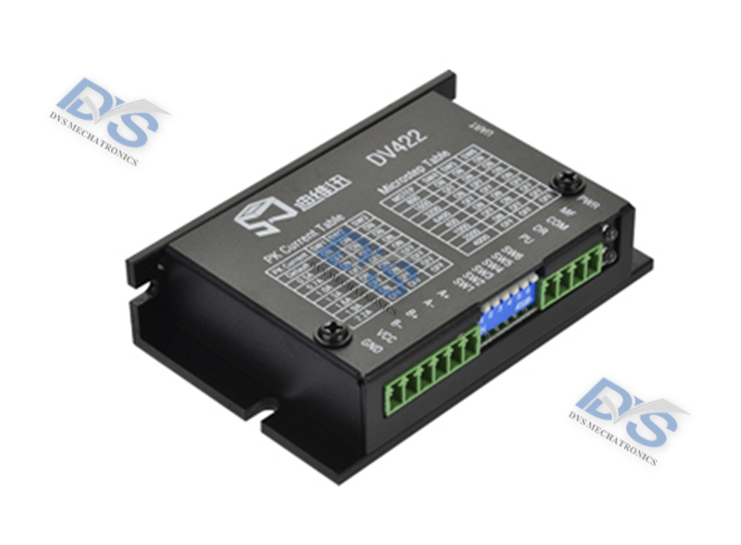
Stepper driver DV422
DV series digital stepper driver
Product Introduction
DV422 is a two-phase hybrid stepper motor driver based on DSP control, and is a new generation digital stepper motor driver. The driving voltage is DC12-36V, suitable for various models of two-phase hybrid stepper motors with an outer diameter of 39-42mm and a current below 2.2A. Smooth operation, minimal vibration and noise. The positioning accuracy can reach up to 6400 steps per revolution. This product is widely used in laser processing equipment, medical equipment, measurement equipment, motor processing equipment, etc.
Technical information
Characteristic:
Featuring 8-speed equal angle constant moment subdivision, with a maximum resolution of 6400 steps per revolution;
The maximum response frequency can reach 200Kpps;
Automatic half current can be set by users. When the step pulse stops for more than 1.5 seconds, the coil current will automatically decrease to half of the set current;
Optoelectronic isolation signal input/output;
The driving current is adjustable from 0.3A/phase to 2.2A/phase, divided into 8 levels;
Single power input, voltage range: DC12~36V;
Driver installation size: 86 × 21 × 56mm3;
Current setting
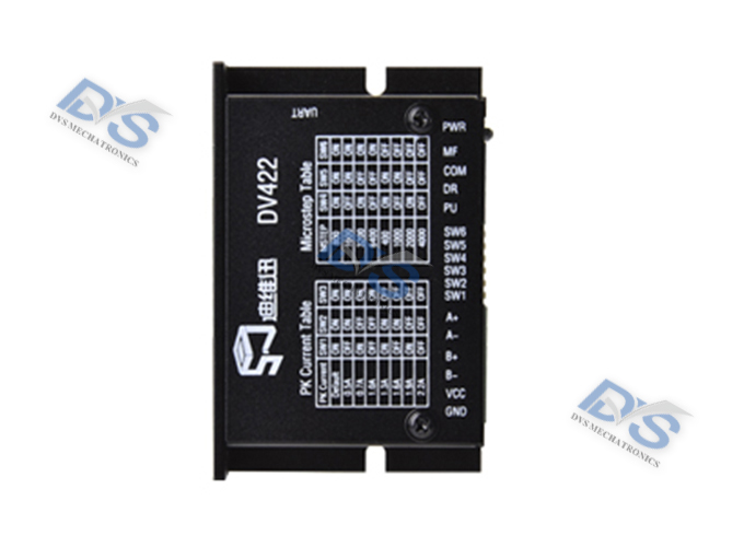
The operating current of the driver is set by the SW1-SW3 dial, and the operating current is the effective output current for normal operation. The setting switch is detailed in the table below:
| Peak current (A) | Default | 0.5 | 0.7 | 1 | 1.3 | 1.6 | 1.9 | 2.2 |
| Operating current (A) | 0.35 | 0.49 | 0.71 | 0.92 | 1.13 | 1.34 | 1.56 | |
| SW1 | ON | OFF | ON | OFF | ON | ON | ON | OFF |
| SW2 | ON | ON | OFF | OFF | OFF | ON | OFF | OFF |
| SW3 | ON | ON | ON | ON | OFF | OFF | OFF | OFF |
Subdivision settings
The subdivision of the driver is set by the SW4-SW6 terminals, with a total of 8 levels. Attached Table: Subtraction (Pulse/Revolution)
| Subtraction | 800 | 1600 | 3200 | 6400 | 400 | 1000 | 2000 | 4000 |
| SW4 | ON | OFF | ON | OFF | ON | ON | ON | OFF |
| SW5 | ON | ON | OFF | OFF | OFF | ON | OFF | OFF |
| SW6 | ON | ON | ON | ON | OFF | OFF | OFF | OFF |
Wiring precautions:
1. The input voltage cannot exceed DC36V;
2. The input control signal level is within the range of+5V~+28V, and there is no need to connect an external current limiting resistor when it is higher than+5V;
3. The falling edge of the input pulse signal is effective;
4. When the temperature of the drive exceeds 80 degrees, the drive stops working and the fault indicator light ALM lights up. Until the temperature of the drive drops to 50 degrees, the drive needs to be powered on again to resume operation. If overheating protection occurs, please install a radiator;
5. The overcurrent (load short circuit) fault indicator light ALM is on. Please check the motor wiring and other short circuit faults. After troubleshooting, it is necessary to power on again to restore;
6. No motor fault indicator light ALM is on. Please check the motor wiring. After troubleshooting, power on again to restore.
External dimensions

Wiring method
Pin Function Description:
| Marking symbols | Function Description | Notes |
| PU | Stepping pulse signal | The falling edge is effective, and every time the pulse changes from low to high, the motor takes one step with an input resistance of 220 Ω Requirements: Low level 0-0.5V, high level greater than 4V, pulse width>2.5 μ S |
| DR | Direction control signal | Used to change the direction of the motor. Input resistance 220 Ω Requirements: Low level 0~0.5V, high level greater than 4V, pulse width>2.5 μ S |
| COM | Input signal common terminal | Connected to the positive end of the signal power supply, the amplitude range is+5V~+28V, which can be driven. When it is higher than+5V, there is no need to connect an external current limiting resistor |
| MF | Motor release signal | When effective (low level), the motor wiring current is turned off, the driver stops working, and the motor is in a free state |
| GND | Power supply negative terminal | Power supply: DC12-36V |
| VCC | Positive end of power supply | |
| A+ | Motor wiring |  |
| A- | ||
| B+ | ||
| B- |
Data download
CONTACT
ADD 1: 555, 5th Floor, Liangji Building, East Ring Road, Fukang Community, Longhua Street, Longhua District, Shenzhen, China
ADD 2: 11th Floor, Building S7, Yantian Tian'an Digital City, Fenggang Town, Dongguan City, China
Tel : +86-755-26998910
E-mail : market-sales@dvsjd.com


Shenzhen Diweixun Electromechanical Technology Co., Ltd
Miss Zhang 13612901214
Phone: 0755-2699891
Email: market-sales@dvsjd.com
Address: 555, 5th Floor, Liangji Building, East Ring Road, Fukang Community, Longhua Street, Longhua District, Shenzhen, CHINA
11th Floor, Building S7, Yantian Tian'an Digital City, Fenggang Town, Dongguan City, CHINA
Copyright @ 2023 Shenzhen Diweixun Electromechanical Technology Co., Ltd. All Rights Reserve 粤ICP备2023019575号


