

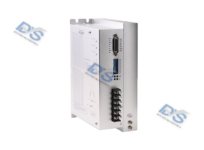
Stepper driver DV3722B
DV series digital stepper driver
Product Introduction
DV3722B is a three-phase stepper motor driver based on DSP control. It is a new generation digital stepper motor driver composed of advanced DSP control chips and three-phase inverter drive modules. The driving voltage is AC80V-290V, suitable for various models of three-phase hybrid stepper motors with currents ranging from 1.3A to 7.0A and an outer diameter of 57-130mm. The driver adopts a circuit similar to servo control principle inside, which can make the motor run smoothly with almost no vibration and noise. At high speed, the torque of the motor is much higher than that of two-phase and five phase hybrid stepper motors. The positioning accuracy can reach up to 60000 steps per revolution. This product is widely used in woodworking carving machines, CNC machine tools, computerized embroidery machines, packaging equipment, ceramic equipment, and laser cutting equipment.
Technical data
Characteristic:
Featuring 16 levels of equal angle constant moment subdivision, with a maximum resolution of 60000 steps per revolution
The maximum response frequency can reach 200Kpps
When the step pulse stops for more than 1.5 seconds, the coil current automatically decreases to half of the set current
Optoelectronic isolation signal input/output
The driving current is adjustable from 1.3A/phase to 7.0A/phase in 16 levels
Single power input, voltage range: AC80V~290V
Phase memory function (note: after the input stops for more than 3 seconds, the driver automatically remembers the current motor phase, and when it is powered on again or the MF signal changes from low level to high level, the driver automatically restores the motor phase).
Current setting
The operating current of the driver is set by terminals D1-D4, and the operating current is the normal output current setting switch (see the table below for details)
| Operating current (A) | 1.3 | 1.6 | 2.1 | 2.3 | 2.5 | 3.0 | 3.2 | 3.5 |
| D1 | OFF | OFF | OFF | OFF | OFF | OFF | OFF | OFF |
| D2 | OFF | OFF | OFF | OFF | ON | ON | ON | ON |
| D3 | OFF | OFF | ON | ON | OFF | OFF | ON | ON |
| D4 | OFF | ON | OFF | ON | OFF | ON | OFF | ON |
| Operating current (A) | 4.0 | 4.5 | 5.0 | 5.3 | 5.8 | 6.2 | 6.5 | 7.0 |
| D1 | ON | ON | ON | ON | ON | ON | ON | ON |
| D2 | OFF | OFF | OFF | OFF | ON | ON | ON | ON |
| D3 | OFF | OFF | ON | ON | OFF | OFF | ON | ON |
| D4 | OFF | ON | OFF | ON | OFF | ON | OFF | ON |
Subdivision settings
The subdivision of the driver is set by terminals D5-D8, with a total of 16 levels. D9 and D10 are functional settings. Attached Table: Subtraction (Pulse/Revolution)
| Subtraction | 400 | 500 | 600 | 800 | 1000 | 1200 | 2000 | 3000 |
| D5 | ON | ON | ON | ON | ON | ON | ON | ON |
| D6 | ON | ON | ON | ON | OFF | OFF | OFF | OFF |
| D7 | ON | ON | OFF | OFF | ON | ON | OFF | OFF |
| D8 | ON | OFF | ON | OFF | ON | OFF | ON | OFF |
| Subtraction | 4000 | 5000 | 6000 | 10000 | 12000 | 20000 | 30000 | 60000 |
| D5 | OFF | OFF | OFF | OFF | OFF | OFF | OFF | OFF |
| D6 | ON | ON | ON | ON | OFF | OFF | OFF | OFF |
| D7 | ON | ON | OFF | OFF | ON | ON | OFF | OFF |
| D8 | ON | OFF | ON | OFF | ON | OFF | ON | OFF |
| D9 | ON: Double pulse. PU is a forward stepping pulse signal; DR is a reverse step pulse signal | |||||||
| OFF: Single pulse. PU is a step pulse signal; DR is the directional control signal | ||||||||
| D10 | Automatic detection switch (receives external pulses when OFF, runs internally at 30 rpm when ON) | |||||||
Note: Customization of fine scores can be made according to customer requirements!
Wiring precautions:
1. When the input voltage is lower than AC80V and higher than AC290V, the driver will automatically protect
2. The input control signal level is 5V. When it is higher than 5V, a current limiting resistor needs to be connected, and the driver comes with a 24V signal interface
3. The falling edge of the input pulse signal is effective
4. The cooling fan of the drive only starts working when the temperature of the drive exceeds 48 degrees Celsius
5. When the temperature of the drive exceeds 80 degrees Celsius, the drive stops working and the fault indicator light ALM lights up. Until the temperature of the drive drops to 50 degrees Celsius, the drive needs to be powered on again to resume operation. If overheating protection occurs, please install a radiator
6. The overcurrent (load short circuit) fault indicator light ALM is on. Please check the motor wiring and other short circuit faults. After troubleshooting, it is necessary to power on again to restore
7. No motor fault indicator light ALM is on. Please check the motor wiring. After troubleshooting, power on again to restore
Corresponding fault symptoms (excluding power light and POW light)
1. Module overcurrent: single red light (ALM light) always on
2. Drive overheating: The red light (ALM light) and two green lights (PU light and DR light) alternate on
3. Undervoltage: The red light (ALM light) and DR light are both on
4. Overvoltage: Red light (ALM light) flashing fast
External dimensions


Wiring method
Pin Function Description:
| Pin number | Marking symbols | Function Description | Notes |
| 1 | PU+ | Input signal photoelectric isolation positive terminal | Connected to a+5V power supply, both+5V and+24V can be driven, and above+5V, a current limiting resistor needs to be connected |
| 2 | PU- | DP9=OFF, PU is the progress pulse signal | The falling edge is effective. Whenever the pulse changes from high to low, the motor takes one step and the input resistance is 220 Ω Requirements: Low level 0-0.5V, high level greater than 4V, pulse width>2.5 μ S |
| DP9=ON, PU is a positive phase stepper pulse signal | |||
| 3 | DR+ | Input signal photoelectric isolation positive terminal | Connected to a+5V power supply, both+5V and+24V can be driven, and above+5V, a current limiting resistor needs to be connected |
| 4 | DR- | DP9=OFF, DR is the direction control signal | Used to change the direction of the motor. Input resistance 220 Ω Requirements: Low level 0~0.5V, high level greater than 4V, pulse width>2.5 μ S |
| DP9=ON, DR is a reverse step pulse signal | |||
| 7 | MF+ | Input signal photoelectric isolation positive terminal | Connected to a+5V power supply, both+5V and+24V can be driven, and above+5V, a current limiting resistor needs to be connected |
| 8 | MF- | Motor release signal | When effective (low level), the motor wiring current is turned off, the driver stops working, and the motor is in a free state |
| 9 | ALM+ | Driver fault output signal photoelectric isolation positive terminal | When the driver experiences overcurrent or overheating faults, the driver outputs a fault signal, which is valid (low level) |
| 10 | ALM- | Driver malfunction good output signal photoelectric isolation negative terminal | |
| 11 | RDY+ | Driver ready to output signal photoelectric isolation positive terminal | The driver status is normal and ready to receive the controller signal. The signal is valid (low level) |
| 12 | RDY- | Driver ready to output signal photoelectric isolation negative terminal | |
| 13 | 24PU+ | Input signal photoelectric isolation positive terminal | +24V drivable |
| 14 | 24DR+ | Input signal photoelectric isolation positive terminal | +24V drivable |
| 15 | 24MF+ | Input signal photoelectric isolation positive terminal | +24V drivable |
| 1、2 | L、N | Power Supply | Power supply: AC80V~290V |
| 3 | NC | Ground wire open | Earth (internal drive housing) |
| 4 | U | Motor wiring |  |
| 5 | V | ||
| 6 | W |
Data download
CONTACT
ADD 1: 555, 5th Floor, Liangji Building, East Ring Road, Fukang Community, Longhua Street, Longhua District, Shenzhen, China
ADD 2: 11th Floor, Building S7, Yantian Tian'an Digital City, Fenggang Town, Dongguan City, China
Tel : +86-755-26998910
E-mail : market-sales@dvsjd.com


Shenzhen Diweixun Electromechanical Technology Co., Ltd
Miss Zhang 13612901214
Phone: 0755-2699891
Email: market-sales@dvsjd.com
Address: 555, 5th Floor, Liangji Building, East Ring Road, Fukang Community, Longhua Street, Longhua District, Shenzhen, CHINA
11th Floor, Building S7, Yantian Tian'an Digital City, Fenggang Town, Dongguan City, CHINA
Copyright @ 2023 Shenzhen Diweixun Electromechanical Technology Co., Ltd. All Rights Reserve 粤ICP备2023019575号


